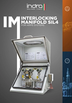
1oo1 Interlocking Manifold
Complete system-level redundancy for ultimate safety integrity
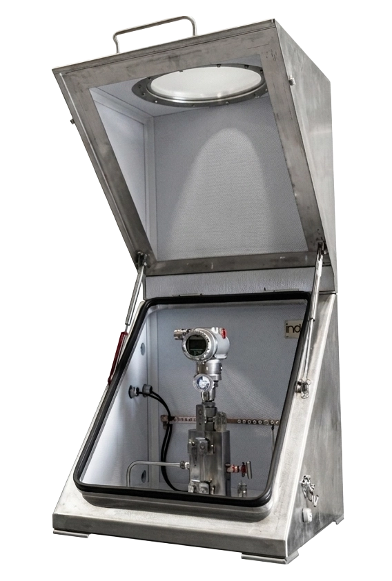
What is 1oo1 Triple Redundant Architecture?
The 10o1 (1-out-of-1) triple redundant configuration consists of threecompletely independent interlocking manifold assemblies, each
operating as a standalone safety system. This architecture provides
the highest level of redundancy by implementing full system
separation across all three voting channels.
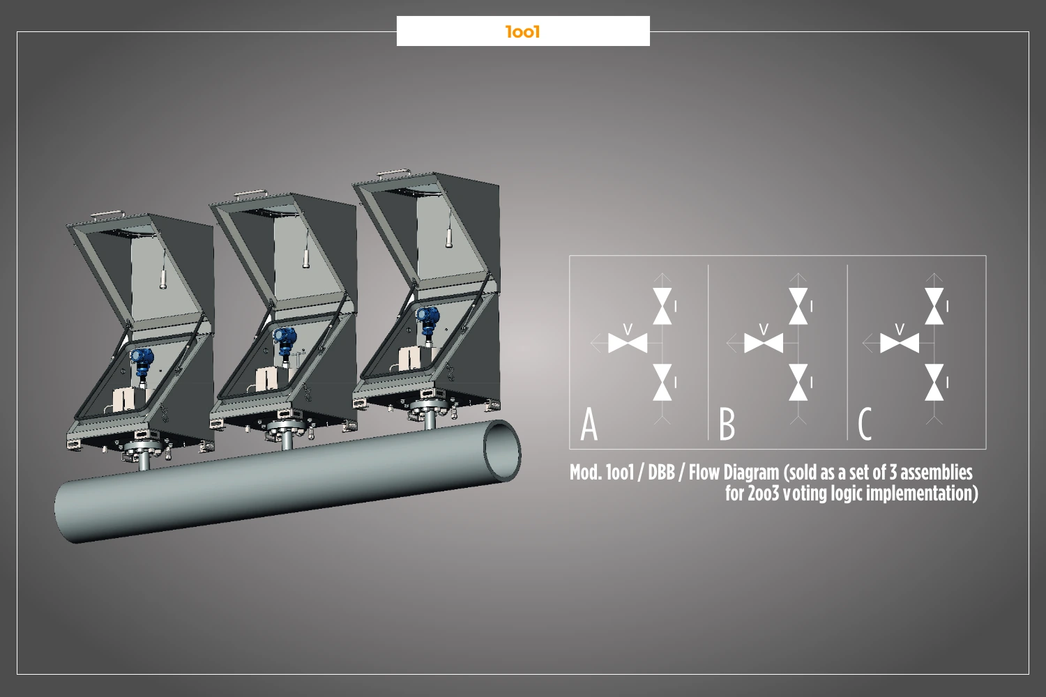
Unlike the integrated 2003 design, each 100l assembly has its own
independent inlet, outlet, sensors, valves, and enclosure. The three
assemblies are installed at different locations and connected to an
external logic solver that implements the 2003 voting algorithm.
Key principle: Complete physical and logical separation between
voting channels eliminates common cause failures and enables
geographically distributed sensing for maximum safety integrity.
✓Complete system redundancy: no single point of failure across entire safety chain
Technical Specifications
- Configuration
Set of 3 independent assemblies (sold as set for 2oo3 voting logic implementation)
- Voting Logic
External 2oo3 logic solver required (not included)
- Inlet Configuration
Three separate flanged inlets
Each assembly: independent process connection- Connections
Flanged (ASME B16.5 / API 6A)
- Bore Size
8 mm | 10 mm
- Pressure Rating
6,000 PSI (420 bar) | 10,000 PSI (690 bar)
- Seal Options
Standard: PTFE
Optional: Graphite- Material
Stainless Steel 316/316L, Duplex, Alloy 625, Alloy 825, Hastelloy, Titanium, 6Mo, Monel 400
All materials NACE MR0175/ISO 15156 compliant- Enclosure per Assembly
Individual IP66-rated enclosure for each manifold
St.St. 316/316L construction- Certification
SIL 4 - IEC 61508 certified (each assembly)
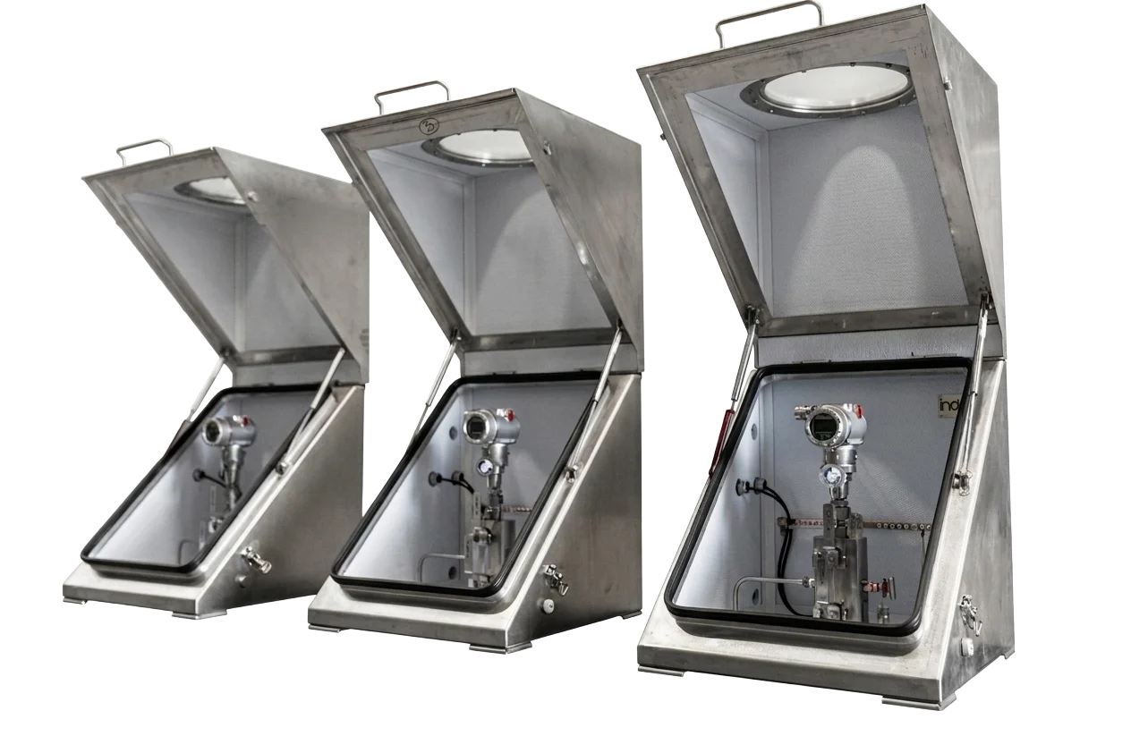
The 1oo1 configuration is supplied as a set of three identical assemblies (A, B, C), each complete with manifold, enclosure, and specified accessories. External logic controller must be provided separately to implement 2003 voting algorithm.
Key Features
Complete Channel Separation
Independent Maintenance
Geographically Distributed
Maximum Safety Integrity
System Configuration
Complete Set Includes
Assembly A: 1001 manifold + enclosure + accessories
Assembly B: 100l manifold + enclosure + accessories
Assembly C: 1001 manifold + enclosure + accessories
Note: Each assembly operates independently. External logic solver required to implement 2oo3 voting algorithm across the three channels.
| Feature | 1oo1 (Set of 3) | 2oo3 Configuration |
|---|---|---|
| Architecture | 3 independent assemblies | Single manifold, 3 sensors |
| Redundancy Level | Complete system redundancy | Sensor-level redundancy |
| Common Cause Failure | Eliminated by physical separation | Single manifold body = potential CCF |
| Geographic Distribution | Yes - spatially diverse sensing | No - single location |
| Installation Complexity | Higher - triple piping required | Lower - single connection point |
| Footprint | Three separate enclosures | Compact, single enclosure |
| Independent Maintenance | Yes - full channel isolation | Limited - shared manifold body |
| Best For | Maximum safety integrity | Space-constrained installations |
Need a more compact solution?
Explore our 2oo3 Configuration for integrated voting logic in a single manifold assembly.
Typical Applications
Major Hazard Facilities
High-consequence installations requiring highest SIL rating with no common cause vulnerabilities
Offshore Production Platforms
Spatially distributed sensing across different platform levels or modules
FLNG Vessels
Critical shutdown systems where geographic diversity mitigates vessel motion effects
Large-Bore Pipeline Protection
Distributed sensing along pipeline sections for comprehensive coverage
Nuclear-Grade Process Safety
Each assembly monitoring different process units feeding common downstream equipment
Multi-Unit Process Plants
Each assembly monitoring different process units feeding common downstream equipment
Need a more compact solution?
Explore our 2oo3 Configuration for integrated voting logic in a single manifold assembly.